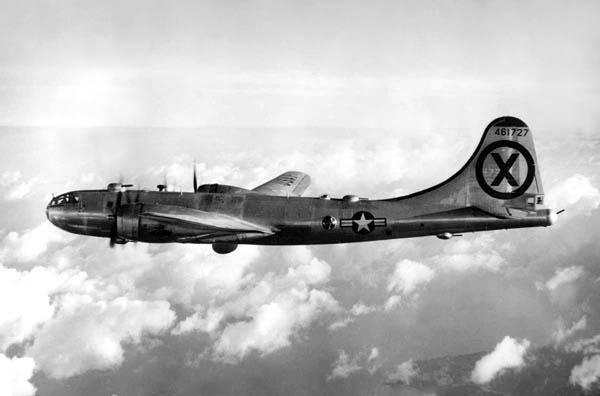
Aerial Photography, a basic understanding of mapping

A Basic Course on Producing Maps from Aerial Photography

The Evolution of Equipment and Procedures, Includes Many Photos

INTRODUCTION: It is my intention to present an article describing in understandable language most of the aspects of aerial mapping. To fully cover all areas of possibilities we would have several very large volumes. So the very name of this article describes it perfectly, it is a BASIC course to give the casual reader an understanding of aerial mapping.

Aerial Photography

WWI saw the emergence of aerial photography as a useful tool to determine troop locations, trenches, ammo storage areas, etc. Although crude, with the photographer hanging over the side of his aircraft, it gave the side with the best photo coverage an advantage in determining their offensive attack plans. WWII saw the need for more sophisticated methods of obtaining photographic coverage. We needed photos of areas to be bombed, airfields, dams, bridges, etc. A most important usage was bomb damage assessment. Bomber Command needed to know the results of bombing raids. Probably our best effort was to modify 118 B-29s to a F-13.

Since the B-29 was pressurized it was necessary for ¾ inch thick glass windows to be installed by Continentals Denver Modification Center. Fitting these windows involved considerable structural work on the airframe. The typical F-13 carried many cameras for high altitude work. The tri-metrogon set up consisted of three cameras, one pointing straight down, and one on each side mounted at an angle to give horizon to horizon coverage. Total coverage of the three cameras was 194 degrees, 7 degrees above each horizon. These were K-17 cameras with between the lens shutters, with a six inch focal length. Resolving power of these cameras was not very good when compared with the lenses of today. The next setup was called the split vertical. The camera mount contained two K-22 cameras with 40 inch focal length. These cameras had focal plane shutters and were mounted side by side to give side lapping coverage. The next setup had an arrangement to install a variety of mounts which could hold a variety of cameras. The K-18 could be used which produced a 9 X 18 inch negative. The K-19 night camera could be installed here with the photoelectric cell. Most of the time a K-17 with a 12 inch FL was used which could be corrected for tip, tilt, and swing. A viewfinder allowed the photographer to determine overlap, and crab. An intervalometer for each camera allowed setting the trip timing to give 60 percent overlap. One special RB-29 had a 100 inch focal length camera mounted in the bomb bay shooting out a side window. The F-13 was built specifically for surveillance and reconnaissance.

F-13 - ¾ inch glass photo windows in RB-29 - Photo ctsy USAF
Flight plan - Exposure stations of mapping aircraft - Photo ctsy W. Mayo

Since the B-29 was pressurized it was necessary for ¾ inch thick glass windows to be installed by Continentals Denver Modification Center. Fitting these windows involved considerable structural work on the airframe. The typical F-13 carried many cameras for high altitude work. The tri-metrogon set up consisted of three cameras, one pointing straight down, and one on each side mounted at an angle to give horizon to horizon coverage. Total coverage of the three cameras was 194 degrees, 7 degrees above each horizon. These were K-17 cameras with between the lens shutters, with a six inch focal length. Resolving power of these cameras was not very good when compared with the lenses of today. The next setup was called the split vertical. The camera mount contained two K-22 cameras with 40 inch focal length. These cameras had focal plane shutters and were mounted side by side to give side lapping coverage. The next setup had an arrangement to install a variety of mounts which could hold a variety of cameras. The K-18 could be used which produced a 9 X 18 inch negative. The K-19 night camera could be installed here with the photoelectric cell. Most of the time a K-17 with a 12 inch FL was used which could be corrected for tip, tilt, and swing. A viewfinder allowed the photographer to determine overlap, and crab. An intervalometer for each camera allowed setting the trip timing to give 60 percent overlap. One special RB-29 had a 100 inch focal length camera mounted in the bomb bay shooting out a side window. The F-13 was built specifically for surveillance and reconnaissance.

Photographic Enlargers

Saltzman photographic enlarger
Saltzman photographic enlarger - Photo by W. Mayo
Wild E-4 rectifying enlarger
Wild E-4 rectifying enlarger - Photo by W. Mayo

The aerial negative could be placed in a photographic enlarger and could produce an image of various enlargement ratios. We will follow the simple procedures to the final sophisticated computerized capability. Accurate measurements cannot be made on a photo enlargement as it is a perspective projection. Enlargers were improved to allow for correction of a negative that at the time of exposure had tip or tilt. Next came the so called rectifying enlarger. The film plane and easel could be tilted but the projected result was still a perspective projection, not useable for measurements. Next came a great improvement when Wild-Heerbrug introduced the E-4. This system solved the Scheimpflug condition electronically, which must be adhered to if the image plane is tilted with respect to the object plane when projecting images through a lens. The Scheimpflug condition states that if a line is drawn through the image plane, the object plane, and the lens plane, then all three lines will intersect at the same point in space. This is so far the best rectification system available. To my knowledge there is only one in use in the U.S.

If the image and object planes are parallel, then the lens plane must also be parallel. If the ground is perfectly flat, then the E-4 enlarger can produce a rectified enlargement from which one could obtain fairly accurate measurements. After all this, it is still a perspective projection, and we must solve the problem of relief in the terrain which will cause scale change. Simple put, you cannot take a measurement on any perspective enlargement that has the normal variation of ground relief. The enlargement will contain various scales as the ground elevation varies. Scale is the ratio of a distance on a photograph or map to it’s corresponding distance on the ground. So, regardless of the sophistication of the rectifying enlarger it still produces a perspective projection. To be able to take measurements we must have an orthographic projection!

Examining a mylar sheet produced on a photographic enlarger - Photo by W. Mayo
Hand scribing, an outmoded method replaced by automatic procedures - Photo by W. Mayo

Orthophotography

An orthophoto is a photograph showing images of objects in their orthographic positions. Orthophotos are geometrically the same as a planimetric map which also shows true orthographic positions of objects. The difference between the two is that the orthophoto is composed of actual images and the planimetric map consist of lines. Since they are planimetrically correct, orthophotos can be used as maps for making direct measurements, angles, and coordinated positions without making corrections for image displacement. This cannot be done with a regular photographic enlargement, which is a perspective projection, if there is any relief.

Wild point transfer device
Wild point transfer device - Photo by W. Mayo
Kern point transfer device
Kern point transfer device - Photo by W. Mayo
Kern Monocomparator
Kern Monocomparator - Photo by W. Mayo

Orthophotomaps are produced through a process called differential rectification, which eliminates image displacement. They are produced on machines called orthophotoscopes, or on specially modified stereoplotters.

Orthophotomaps are produced by grouping several orthophotographs together to form an absolute orientation in X and Y. Contours and spot elevations can be superimposed on a orthophoto, producing a topographic orthophotomap.

Basically, instruments produce orthophotoscan profiles of the terrain of a stereomodel at uniformly spaced increments, thereby exposing the orthonegative in a series of narrow strips each having a width exactly equal to the spacing between adjacent profile scans.

So we have two methods of producing photo enlargements. No photo made on any type of enlarger can correct for changes in elevation of terrain, and will result in variations of scale as the ground relief changes.
The enlarger will always produce a perspective projection. The orthophoto is an orthographic projection which corrects for relief in terrain, and can be used as a map from which measurements can be taken.

Zeiss makes a high precision photogrammetric scanner designated the SCIA Precision Scanner. With it’s outstanding seven micron resolution and dimensional stability it can produce high resolution digital imagery and precise orthophotos.

Aerial Cameras

Two Zeiss RMKA/15/23 and a RMKA/30/23 Precision Cameras owned by Bosworth Aerial Surveys
Two Zeiss RMKA/15/23 and a RMKA/30/23 Precision Cameras owned by Bosworth Aerial Surveys - Photo by W. Mayo
Wild RC-8 Aerial camera installed in twin Beach
Wild RC-8 Aerial camera installed in twin Beach. - Photo by W. Mayo
Zeiss RMKA/15/23 in Cessna 195
Zeiss RMKA/15/23 in Cessna 195 - Photo by W. Mayo

The cameras used during the Korean War period were barely acceptable for their intended purpose. Basically they lacked resolving power, the ability to record minute detail. These cameras now of course are obsolete and have long since gone to the junk yard. These cameras were mostly K-17 type, K-22, K-18, K-19, and K-38. Through the years there were minor improvements in military cameras with the introduction of the KC-1 and KC-1B which had a planigon lens. Wild-Heerbrug introduced the RC-5, then the RC-8. Zeiss developed the RMK/15/23. These still were not “distortion free” cameras. Finally Zeiss introduced the RMKA/15/23, which for years was accepted by the mapping industry as the most precision camera available, and many are presently being used satisfactorily. Wild-Heerbrug came out with the RC-10 but mapping companies generally preferred the Zeiss.

I had the pleasure to personally visit the Zeiss factory, the Wild factory, and the Kern factory in Europe with my boss Bill Bosworth. I was able to actually use the stereoplotters, rectifiers, and observe the complete manufacturing process of cameras and other equipment. We were impressed with the Wild E-4 rectification system and their A-10 analog stereoplotter. Mr. Bosworth purchased both systems, a very large investment. The A-10 plotter will be discussed later. When the analytical plotter was developed we compared the Zeiss to the Wild BC-2, and selected the BC-2 as better for our usage. These plotters also will be discussed in “Stereoplotters”. As for the cameras we were already using the Zeiss RMKA/15/23. Mr. Bosworth also owned a rare RMKA/30/23 12 inch focal length, which was used with the E-4 system. The 12 inch camera reduced image displacement.

Now a new chapter has emerged on the camera scene. We now have a system so sophisticated it almost defies description. The new camera is a Zeiss RMK TOP 15 high precision aerial mapping system which utilizes a T-AS gyro-stabilized suspension mount and T-MC Forward Motion Compensation magazine. It is difficult to imagine but at the time of exposure the film actually moves in relationship to the moving image. This is image motion compensation. A menu driven computer control system controls the set up. The camera has less than three microns distortion. So since the old K-17 we have taken a giant step in sophistication with this remarkable camera.

Stereoplotters

Kern PG-2 analog stereoplotter
Kern PG-2 analog stereoplotter - Photo by W. Mayo
Kern PG-3 analog stereoplotter in Aarau, Switzerland
Kern PG-3 analog stereoplotter in Aarau, Switzerland - Photo by W. Mayo
Wild A-10 analog stereoplotter
Wild A-10 analog stereoplotter - Photo by W. Mayo
Galileo Santoni model III analog stereoplotter
Galileo Santoni model III analog stereoplotter - Photo by W. Mayo
Galileo Santoni model IV analog stereoplotter
Galileo Santoni model IV analog stereoplotter - Photo by W. Mayo
Full photo of the huge Wild A-10 analog stereoplotter. Note TV Camera mounted on coordinatograph
Full photo of the huge Wild A-10 analog stereoplotter. Note TV Camera mounted on coordinatograph - Photo by W. Mayo

The most important piece of equipment used in map making is of course the stereoplotter. There are two basic types of stereoplotters, projection and optical. While the projection plotter in no longer used we will discuss it because for years it was all we had.

The projection plotter: Diapositives of a stereopair are placed in projectors and illuminated from above. The light rays are projected through the projector lenses and intercepted below on the platen. The function of the viewing system is to enable the operator to view the stereomodel three-dimensionally. The left eye views only the overlap area of the left photo while the right eye sees only the overlap area of the right photo. The anaglyphic system uses red and blue-green filters to separate the left and right projectors. A blue-green filter is placed over the source of light of the left projector and a red filter over the right projector. If the operator wears a pair of spectacles placing a blue-green filter over his left eye and red over the right eye, he will be able to see the stereomodel in three dimensions. Another variation of this system is called the SIA, or image alternator. This system does away with the glasses. Another system is called the PPV which uses polarizing filters instead of colored lenses. The optical train plotter creates a true three-dimensional model from which measurements are taken, by projecting the light rays optically through an optical train to a binocular for viewing.

Relative orientation is a process in which the two projectors are oriented so that diapositives have the exact relative angular orientation to each other in the projectors that the negatives had in the camera at the time of exposure.

After relative orientation, the next step is the absolute orientation. This process involves scaling and leveling the model to given horizontal and vertical control. This description can be applied to the old Kelsh plotter.

We have covered the projection plotter. The next plotter for discussion is the Analog Plotter. The analog plotter utilizes an optical train to view the image. Relative orientation is done manually using six basic projector motions : Kappa, Phi, Omega, X, Y, and Z. Kappa is swing, Phi is tip [ in line of flight] and Omega is tilt[ across the line of flight]. Like all stereoplotters it uses the floating mark principle to trace planimetric detail and to draw contours and make spot elevations. The vertical and horizontal information can be transmitted to the computer for storage. Movements from the plotter can be transmitted to the plotting table by means of a coordinatograph, pantograph, or electronically.

Although this type of machine is also aging and somewhat lacking in performance compared to the analytical plotter, many companies are still using them. Some examples of the old analog plotters are the Gallileo Santoni model III, IV, and V. These have been out of production for years and they continue with questionable capability. Others are the Kern PG-2, Wild B-8 and A-10. The A-10 with a good operator is still capable of producing a topographic map which will meet National Map Specs. It is only a matter of time and these also will go the way of the Kelsh plotter.

The Analytical Plotter

Wild BC-2 Analytical Plotter with automatic table
Wild BC-2 Analytical Plotter with automatic table - Photo by W. Mayo
Wild BC-2 Analytical Plotter
Wild BC-2 Analytical Plotter - Photo by W. Mayo
Automatic scribing with the automatic plotting table on the BC-2
Automatic scribing with the automatic plotting table on the BC-2 - Photo by W. Mayo

The introduction of the Analytical Stereoplotter was perhaps the greatest advance ever made in photogrammetry. Two companies produced the plotters, which made the old analog system completely obsolete. Wild-Heerbrug produced the BC-2 which was a real masterpiece. I had the pleasure of operating the BC-2 for over ten years. Zeiss produced the C-100, the P1 Intermap, and the P3 and P33 Planicomp configured with superimposition. The analytical plotter forms neither an optical nor projection image. Basically an analytical plotter is a stereocomparator which forms a mathematical model. A computer solves orientation elements and drives the coordinatograph for plotting. As mentioned previously volumes can be written describing the capabilities of the analytical plotter. It is difficult to mention only a few of these. There are numerous systems involved, all computer driven. One utilizes an automatic electronic plotting table. Movements in the stereoscopic model are transferred to the table, and recorded in a file in the computer. The automatic table performs a most important and varied task. The coordinatograph not only plots the movements from the plotter, since every movement is recorded in a file the computer controlled unit can replot any portion of the map at any scale. This makes the old hand method of scribing a thing of the past. The table can scribe any area at an incredibly fast speed. Obviously the capabilities of the automatic table are more than described here. Another method utilizes the superimposition of the contours over the model image in the plotter. Not only can the electronic table plot all information gathered in the computer, there are drum plotters which can also be used to quickly plot a finished product at any scale. Once you have used the analytical system it makes you wonder how you were ever able to accomplish anything using the old system.

Very simply put, the stereoplotter is an instrument with which an operator can see a three dimensional image and by moving the microscopic black dot he can draw planimetric features and contours. Contours are lines of equal elevation, and by moving the “floating dot” and keeping it perfectly on the ground he can produce a contour. The area that can be compiled is called the neat model. Two successive negatives overlapping each other by 60 percent will produce stereoscopic coverage in the overlap area.

Volumetric Calculation

The stereoplotter can be used to compute the actual volume of an area. Many different methods are used. One is to establish a base line and cross sections. By digitizing a series of computer generated spot elevations, we can calculate the area of each “slice” by using the average end area formula. As mentioned there are numerous methods and software programs which will compute the cubic yards of an area.

Triangulation

Photogrammetric control extension, or bridging, can yield satisfactory accuracy for computer generated horizontal and vertical photo control, and at a substantial savings over field work. There are two broad categories, analytical and analogical. Analogical involves a manual method using the stereoplotter, however this procedure is practically never used now. The analytical method is the preferred method using a monocomparator or a stereocomparator to measure photocoordinates of corresponding points on a stereopair of diapositives. Fully analytical triangulation corrects for film shrinkage or expansion, compensates for radial lens distortions, corrects for atmospheric refraction, corrects for earth curvature, and reduces the measured coordinates from fiducial axis systems to an axis system with origin at the principal point. This method is referred to as the polynomial method of strip and block adjustment.The most accurate method is called the simultaneous bundle block adjustment. In this procedure all equations for an entire block of photographs are formed and solved simultaneously. By solving both control and pass point equations simultaneously, a numerical relative and absolute orientation of all stereomodels is achieved. These equations are then solved by the least squares adjustment. The bundle technique is more rigorous than the polynomial method.

An area to be mapped requires known coordinates and vertical elevations of points on the ground. By relatively adjusting all the photos together, we can then position the entire job over the control points. The number of control points can be reduced substantially by using triangulation. The computerized bundle adjustment makes an absolute orientation of all models for the best fit to the reduced number of control points.

Close Range Photogrammetry

Wild RC-8 aerial camera mounted to photograph an auto fender for close range digitizing
Wild RC-8 aerial camera mounted to photograph an auto fender for close range digitizing - Photo by W. Mayo

Close Range, or terrestrial photogrammetry refers to photography exposed on the surface of the earth as opposed to “aerial photography”. There is a long list of uses for this procedure, such as traffic accidents, dentistry, criminology, anthropology, architecture, medical X ray, conservation of historical monuments, highway engineering, bridge and tunnel construction, and ship and aircraft construction to name only a few. There are many different photographic techniques in obtaining negatives for close range usage. Two cameras mounted side by side will of course produce a stereopair of negatives. One camera exposed in two locations can produce the same results, or one stationary camera photographing an object mounted on an easel which is moved to two positions. The stereopair can be placed in a stereoplotter and using a technique similar to that required in producing aerial maps can produce whatever results are needed, such as spot elevations, cross sections, or planimetric detail.

Two examples of the use of close range are: traffic accidents and shipbuilding. It is impossible to have a flyover on every accident, so negatives produced on the ground can provide the capability of obtaining accurate measurements. This cannot be done with regular photography. In shipbuilding in some instances it is important to build the ship in parts and in different places. Using close range procedures coordinates can be created which will guarantee a proper fit when units are joined. Coordinates can be generated of all steam pipes and various equipment before installation to make sure that piece of equipment will fit when installed.

Aircraft

This AT-11 was one of the best in it's day
This AT-11 was one of the best in it's day - Photo by W. Mayo

Types of aircraft used for aerial photography is a very interesting subject. We have already covered the RB-29 or F-13. There is no end to the list of desirable aircraft. The AT-11 served for years, but could not accept the new cameras in the nose section. Cessna aircraft are excellent, such as the 180, 185, and the turbo-charged 206. Learjet is great if money is no object.

Piper aircraft are good, with the Geronimo leading as the best mapping plane. To take an aircraft and cut a 24 inch hole in the bottom sometimes requires rerouting cables which is a costly job. So a Piper, Cessna, Lear, it just depends on ones personal preference. Also the type of work will determine the plane: altitude, size of project , number of cameras, etc. All these things must be considered before choosing a Cessna 320, or a Geronimo.

Wayland Mayo and Cessna 195 mapping airplane
Wayland Mayo and Cessna 195 mapping airplane - Photo ctsy W. Mayo
This highly modified Geronimo is a first class STOL mapping aircraft
This highly modified Geronimo is a first class STOL mapping aircraft - Photo by W. Mayo

Three Outstanding Aerial Photos

Mt. Cotopaxi in Ecuador taken from 20,000 ft.
Mt. Cotopaxi in Ecuador taken from 20,000 ft. - Photo by W. Mayo
727 heading for North Korea from Yokota AFB, later shot down by Migs
727 heading for North Korea from Yokota AFB, later shot down by Migs - Photo by W. Mayo
Mt. Fuji, taken from 20,000 ft. returning from mission in Korea
Mt. Fuji, taken from 20,000 ft. returning from mission in Korea - Photo by W. Mayo

Wayland Mayo is a Certified Photogrammetrist, and a Professional Surveyor and Mapper [retired] State of Florida.

Wayland Mayo

Pin It on Pinterest